AF817S10 High Bride System Accessories Demo Didactic Equipment Automobile Training Equipment
AF817S10 High Bride System Accessories Demo Didactic Equipment Automobile Training Equipment For Vocational Training Center, Technical Institution, Engineering University, TVET Schools.
- Description
- Inquiry
Description
AF817S10 High Bride System Accessories Demo Didactic Equipment Automobile Training Equipment
1. Product structure
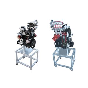
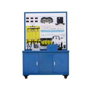
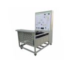
The comprehensive training platform for automobile gasoline-electric hybrid system is based on Toyota’s original gasoline-electric hybrid engine and electronic transmission axle. Composition structure and working process of hybrid engine.
The comprehensive training platform for automobile gasoline-electric hybrid system is suitable for the teaching needs of gasoline-electric hybrid engine and maintenance training in middle and higher vocational technical colleges, general education colleges and training institutions.
2. Features
1. A real and operational gasoline-electric hybrid engine fully demonstrates the composition, structure and working process of the gasoline-electric hybrid engine.
2. The panel of the training platform is made of high-grade aluminum-plastic panels with a thickness of 4mm, which are corrosion-resistant, impact-resistant, pollution-resistant, fire-proof, and moisture-proof. Comparing the circuit diagram and the real object of the hybrid electric engine, understand and analyze the working principle of the control system.
3. The panel of the training platform is equipped with automotive instruments and multi-function display screens, which can display real-time changes in parameters such as power transmission process, vehicle speed, etc., and fault indicators of the electronic control system.
4. There are detection terminals installed on the panel of the training platform, which can directly detect the electrical signals of the pins of sensors, actuators, engine control units, automatic transmissions, hybrid power units, and power supply control units on the panel, such as resistance, voltage, and current. , frequency signal, etc.
5. The training platform is equipped with a diagnostic seat, which can be connected to a special car decoder to perform self-diagnosis functions such as reading fault codes, clearing fault codes, and reading data streams for electronic control systems such as engines, automatic transmissions, hybrid power, and power supplies.
6. The equipment frame is built with integrated all-aluminum alloy profiles, oil-resistant, corrosion-resistant and easy to clean. The table is 30CM wide, durable and rust-free, with 4 universal casters with self-locking devices for easy movement.
7. The training platform is equipped with a throttle control device, which can facilitate the acceleration and deceleration of the engine.
8. The training platform is equipped with installation protection devices such as a main power switch, a water tank protective cover, and a flywheel protective cover.
9. The base of the training platform is welded with steel structure, and the surface is treated with spraying process, with self-locking caster device, which is flexible, safe, reliable, durable.
1. Analysis of new energy vehicles
2. Development of new energy vehicles in the future
3. Basic knowledge of electric vehicles
4. Basic structure and working principle of electric vehicles
5. Electric vehicles and hybrid vehicles
6. Structure and principle of battery electric vehicle
7. Electric vehicle principle maintenance fault detection
8. Pure electric vehicle power system
9. Pure electric vehicle assembly and adjustment process
10. Pure electric vehicle motor and its controller
11. Pure electric vehicle electronic control technology
12 High Voltage Principle Design of Pure Electric Vehicle
13. Pure electric vehicle drive scheme
14. Introduction to electric vehicle transmission system
3. Technical specifications
1. Dimensions (mm): 1800×1200×1800 (length×width×height);
2. Panel dimensions (mm): 1700×1080mm (length*width);
3. Mobile casters: 300*90mm;
4. Working temperature: -40℃~+50℃;
5. Fuel tank volume: 12L;
6. Gasoline-electric hybrid engine and electronic transmission axle: Toyota Hybrid
4. Training (experimental) project
1. BMS composition and function working principle of battery management system, power battery pack (BMS) fault analysis and diagnosis.
2. Safety precautions for high-voltage system operation, high-voltage connector plugging and unplugging methods, and knowledge of maintenance switches.
3. Leakage sensor, gear switch, P-shift switch structure principle function testing training.
4. Inverter controller assembly structure and working principle, driving motor structure and working principle training.
5. Demonstration of the working mode of the gasoline-electric hybrid vehicle.
6. Demonstration of the power transmission route of the gasoline-electric hybrid drive.
7. Training on the structure and working principle of brake energy feedback.
8. Oil-electric hybrid inverter structure and working principle, diagnosis and testing training.
9. Oil-electric hybrid engine structure and working principle, diagnosis and testing training.
10. Electronic accelerator pedal, one-button start switch structure principle function testing training.
11. Hybrid vehicle control strategy system structure and principle cognition, function dynamic demonstration, fault simulation, fault detection and maintenance, fault diagnosis and elimination.
Training Programs to be Performed:
a. Hybrid Electric Vehicle (HEV) architecture
b. Electric permanent magnet synchronous motor (PMSM)
c. Battery
d. Electric motor ECU
e. Engine fuel ECU
f. Data network
g. Operation modes
h. engine starting
i. low and high speed cruising
j. light and full acceleration
k. deceleration and braking
l. reverse
m. Regenerative braking
n. Battery charging
Technical Specifications:
o. The system should arrange on a wide silk-screen, panel should be provided with:
p. Color silk screen panel
q. Test jacks of 2 mm
r. Pushbutton ignition key
s. Selection of the operational conditions with potentiometers and buttons
t. Display of state of the system with both single and bargraph Leds
u. Automatic speed lever PRNDB
v. Battery test points
w. Impact simulation pushbutton
x. Dynamic display of the parameters, on the computer screen, with software of high graphic performance
y. USB connection with the computer
z. Power supply: 230 Vac 50 Hz single-phase – 50 VA