
AFF058 Fluid Mechanics Experimental Plant Teaching Equipment Hydrodynamics Laboratory equipment
Description
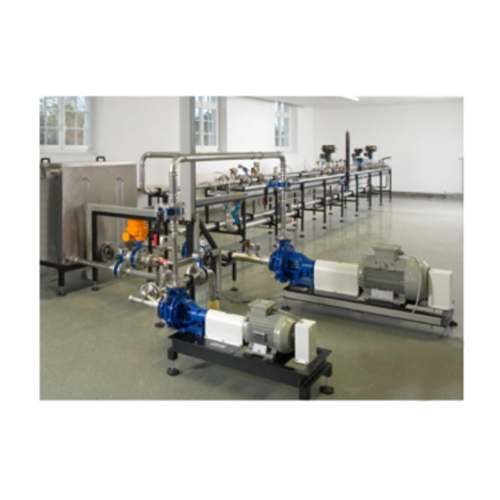
AFF058 allows precise investigations of different fluidic problems. The large scale of the experimental plant and the use of industrial components deliver results close to reality. The dimensions of the experimental plant allow sufficient inlet and outlet sections for the flow formation.
HM 124 consists of several assemblies: a pump station with two differently sized centrifugal pumps, a priming tank, two measuring sections – each of five meter length – one with a nominal diameter of 50mm (DN50), the other one with 25mm nominal diameter (DN25), and a control room consisting of a control console and data acquisition. Optionally the experimental plant may be operated with an additional tank on a lower level for higher suction heads. The complex system may be adjusted in a flexible way to the local facilities.
Many interchangeable piping elements allow an extensive experimental range. Using the measuring section DN50, the Kv values of different control valves can be determined conforming to standards, e.g. an electropneumatic control valve. A transparent pipe section with ink injection allows to observe the flow in the wake of a fitting or a valve. To measure pipe resistances, pipe sections with different surface roughness are inserted in the measuring section DN25.
A pressure controlled system controls the system pressure, the flow rate is controlled by a flow controller and the speed of the pumps. The pumps are operated by the control console. Thus the mapping of pump characteristics is comfortably done.
The experimental plant is equipped with numerous sensors for pressure, flow rate, temperature, speed and torque. The measured values can be read on digital displays. At the same time, the measured values can also be transmitted directly to a PC via USB. The data acquisition software is included.
Specification
1.comparison and calibration of different flow meters
2.water circuit with tank, pump and valve to adjust flow rate
3.2 measuring locations for vertical or horizontal installation of the flow meters under test
4.electromagnetic flow rate sensor for reference measurement
5.1 differential pressure sensor and twin tube manometers for measurement of pressure losses
6.DC voltage source to supply the flow meters with auxiliary power
7.flow meters available as accessories