AFP018H PLC Controlled Pneumatic And Hydraulic Training Test Bench Teaching Equipment Hydrualic Circuit Trainer
AFP018H PLC Controlled Pneumatic And Hydraulic Training Test Bench Teaching Equipment Hydrualic Circuit Trainer
- Description
- Inquiry
Description
AFP018H PLC Controlled Pneumatic And Hydraulic Training Test Bench Teaching Equipment Hydrualic Circuit Trainer
Using Allen Bradley (Rockwell Automation) PLC Flat-form
Power Supply: 220VAC, single Phase, 60Hz.
Brief introduction:
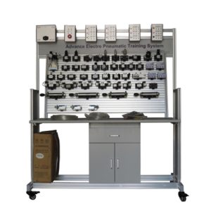
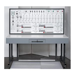
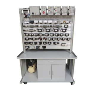
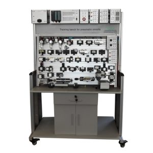
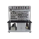
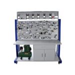
The experimental device uses double-sided structure, ie an experimental table provides places for doing pneumatic and hydraulic test experiment for two groups of four students. It can simultaneously do double-sided comprehensive pneumatic and hydraulic experiments, optimizing and sharing resources and improving products’ performance. Its overall structure is simple and practical.
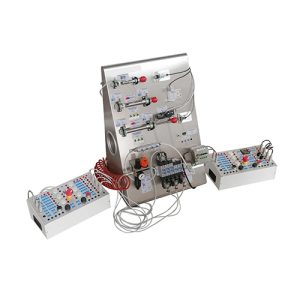
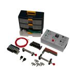
The training equipment is iron double matte dense spray pattern, which is beautiful, durable and practical. The basic configuration is as following: 1 set of pneumatic training components; 1 set of pneumatic PLC control module; 1 piece of low noise air compressor; 1 set of hydraulic training components; 1 set of hydraulic PLC control module; 1 piece of hydraulic test pump. The optional configuration is the computer.
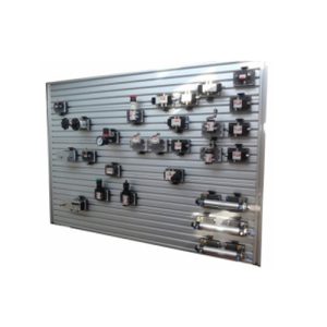
This training system uses a dedicated independent hydraulic test pump with variable speed DC motor system with oil pressure setting function. You can set safe working pressure of output oil pressure. With all common hydraulic components: Each hydraulic component is equipped with mounting plate, which can be easily and freely placed in the aluminum alloy hydraulic components on the panel (the panel with “T” slot in the form of aluminum alloy structure). Oil lap using quick-change connectors; convenient disconnect without leakage.
With this set of training equipment, you can do pneumatic control and hydraulic control circuit and its corresponding basic application experiments. It can also be integrated with each other to carry out the following experiment: realized pneumatic – electric control, pneumatic – hydraulic control, electric – fluid control, and pneumatic – electric – hydraulic integrated control.
Product Detail
Technical parameters of pneumatic part
- Pneumatic components
- Main technical parameters:
2.1 Power: AC 220V 50HZ
2.2 DC power: input AC220V, output DC 24V/2A
2.3 Air compressor
2.4 Motor power: 250W power: AC220V
2.5 Nominal capacity: 10L
2.6 Rated output voltage: 1Mpa
2.7 Training Equipment dimensions: 1500mm*900mm*1700mm
- Basic experimental Pneumatic circuit
3.1 single-acting cylinder commutation circuit
- double-acting cylinder commutation circuit
- single-acting cylinder speed control loop
- double-acting cylinder-way flow control loop
- double-acting cylinder bi-speed circuit
- the speed loop for access
- buffer circuit
- the secondary pressure control loop
- high and low voltage conversion circuit
- counting loop
- the delay loop
- overload protection circuit
- interlock circuit 1
- single-cylinder reciprocating control loop
- single-cylinder reciprocating continuous loop
- linear cylinders, rotary cylinders loop sequence of actions
- multi-cylinder sequence of actions loop
- twin synchronized action loop
- four-cylinder linkage loop
- the unloading circuit
- gate circuit type shuttle valve applications
- quick exhaust valve application circuit